ASTM is an international standards organization that is located in the United States of America. The purpose it was introduce to the industry is to publish technical standard agreements for various materials, product, systems and others. Among the ASTM standards that are often use in the industry is ASTM D2719 Test Standard .
ASTM D2719 Test Standard
Description For ASTM D2719
ASTM D2719 is an international test standard design to determine the shear through-the thickness properties of structural panels associated with shear distortion of the major axis.
Structural panels in use include plywood, wafer board, oriented strand board, and composites of veneer and of wood based layers.
The choice of test method will be determine in part by the purpose of the tests, characteristics of test material, and equipment availability.
In general, Test Method B or C for large specimens is preferred when equipment, amount of test material, and experimental plan permit.
Test Method A:
Small Panel Shear Test-This test method is suitable for testing small samples of uniform material including investigations of the effects of grain direction or orientation and of many raw materials and manufacturing process variables which influence shear properties uniformly throughout the specimen
Test Method B:
Large Panel Shear Test-This test method is regarded as giving the most accurate modulus of rigidity and is therefore recommended for elastic tests of materials to be use in stress analysis studies of test structures.
This test method also yields excellent shear strength values for clear material.
Test Method C:
Two-Rail Shear Test-This test method is applicable to a wide variety of materials and problems.
The specimen fabrication and test procedures are somewhat simpler than in Test Methods A and B and The specimen is free to shear parallel to its 24-in. (610-mm) length dimension anywhere within the 8-in. (203-mm) width between rails.
Specimen For ASTM 2719
1. Plywood material
Jigs For ASTM 2719
Test method A
1. Roller bracket
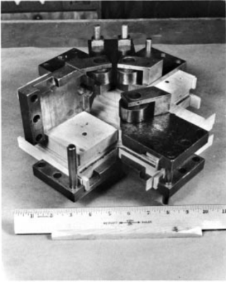
A specimen having a square shear area bounded on each side by solid wood blocks glued to both sides of the specimen is loaded in compression along one diagonal in a conventional testing machine and Forces are apply to the glue-on blocks through a roller bracket assembly which causes the resultant forces to act collinearly with the edge of the shear test area.
This loading method most nearly produces uniform pure shear.
Test method B
1. Loading jig assembly
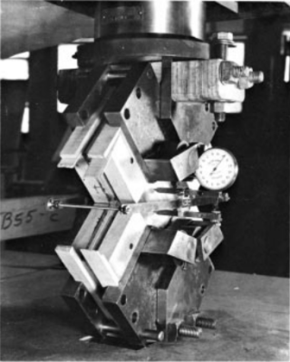
A specimen having a square shear area is loaded through heavy lumber rails glued to both sides of the specimen at all four edges of the shear area and Loading by a system of pins and yokes apply forces to the rails having a resultant acting at the inside edge of the shear area.
Test method C
1. Two rail
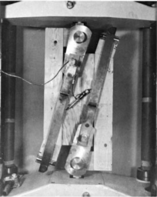
A specimen having a rectangular shear area 8 in. (203 mm) wide by 24 in. (610 mm) long is loaded through heavy lumber or steel rails bounding the long edges only and The short ends of the specimen are not loaded or restrained.
Loading of the rails is such that moment is zero at a section midway between rails and increases slightly as the rails are approach and The centre two thirds of the shear area is subject to nearly constant shear stress which falls to zero at the free ends.
Type of UTM machine
We recommend using UTM machines with a capacity of 5kN-600kN and It depends on the strength of the materials and We also recommend using dual-column types.
1. VEW 2308
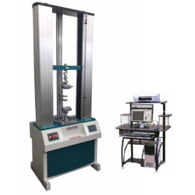
The machine is design by mechanical-electrical integration, the composition of the force-measuring Sensor, transmitter, microprocessor, mechanism of load drive, computer and color inkjet printer.
The high-precision electronic motor can be set to five-speed, the components are connect by plug-way, Floor-standing models, it is taken account of modern industrial design and ergonomics in modelling and Coating and It can be tested with all the materials in the stretch, compression, bending, shear, embedded relay, Peeling. tearing, crack, etc, such as rubber, plastics, leather, metal, nylon wire, fabric, paper, aerospace, packaging, construction, petrochemical, electrical, vehicle, etc.
The implementation of standards and standard configuration:
- GB/T4689.20-1996 Measuring fastness of leather’s adhesion
- QB/T2710-2005 Measuring leather’s expansion and the rate of elongation
- QB/T2711-2005 measuring tear force of leather
- QB/T2712-2005 measuring leather’s strength and stretch of spherical crack test
Test Procedure
Test A- small panel shear test
1. Apply the load by special steel loading blocks which articulate with the rollers and pins attached to the test specimen.
2. The angle between faces of the loading block shall be 90° and between each face and the base the angle shall be 45°.
3. A spherical bearing block, preferably of the suspended, self-aligning type, shall be employed in the loading system.
4. Apply the load continuously throughout the test with a uniform motion of the movable head of the testing machine equal to 0.0025 in./in. of test area diagonal length/min (0.0025 mm/ mm/min) corresponding to a shear strain rate of 0.005 in./in./ min (0.005 mm/mm/min) within a permissible variation of 625 %. 5.3.1.
Load each of the eight reinforcing blocks through roller brackets clamp to the reinforcing block across its width or attached by other means and applying a compressive force to the end of the reinforcing block through a surface contact area of at least 0.75 in.2 (484 mm2 ).
Test B- large panel shear test
1. Load the specimen loading jig assembly in tension.
2. The resultant of forces apply to a pair of rails shall be a single force acting at, and parallel to, the edge of the shear area.
3. If the ends of rails are compression loaded, the jigs shall restrain any tendency for the rails to deflect laterally from the plane of the specimen.
Test C- two rail test
1. The resultant of forces apply to a pair of rails shall be a single force acting along the longitudinal axis of the test specimen both in the plane of the specimen and in the thickness direction;
2. Load application shall minimize the magnitude of both lateral loads to the rails and bending moments;
3. Loading of the fixture specimen assembly shall be in tension between testing machine crossheads by separating the crossheads at a constant rate; and
4. Spherical seats, two-way pivots, or other devices shall be use to ensure approximately equal division of major compressive loads to the two rails on opposite sides of the panel.
Measurements
1. Calculate maximum shear stress or shear stress
2. Calculate modulus of rigidity from deformation data below the proportional limit